1. Tall Wood House
Prepare Stage
The selected design element is to show how the Glue-Laminated Timber columns connect to the CLT floor plate. I decide to make a 1: 5 detail model.
I researched a lot about this building, and find the right structure system.

The construction picture
Then I make a digital model

At the very beginning, I make a digital model for the whole building and want to make a 1: 500 model because it is the tallest timber structure building in the world at the moment. And I give it up finally because in this scale I can only show the relationship between different members and how it looks like, I can't present how they connected and the why this building is so stable.
Therefore, I decided to make a 1:5 detailed model.
The metal connected part, I first tried to used metal plate to make it.

Cutting the metal plate in the right size.


Using an electric drill machine to drill hole on the metal plate and sanding it.


Then using this tool to bend the metal plate.

Using electro welding to connect metal plates together.

Finally I get a metal connection....
BUT
I give it up ..............

The connection is very complex that the upper column, lower column, and floor plate all connected to the junction, the metal connection I made can only be connected to one side and it is too small that it is very hard to represent all the details.....
So I make a digital model on rhino

And 3D print the metal part.
Sorry, I didn't take a picture...

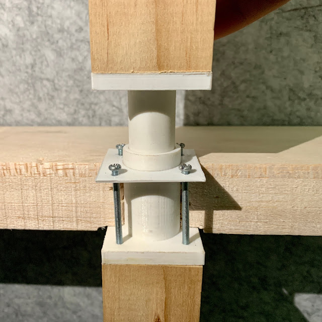
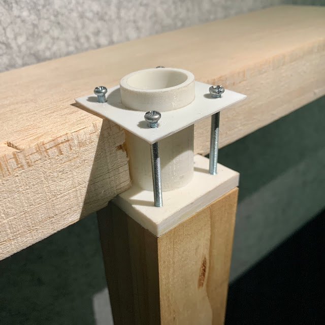
The 3D print one can nicely show all the detail.
I can even assemble them like in real life.

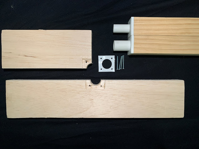
By the way, I found that the CLT panel is made by multi-layer timber plates.
I use 5 layers of balsawood and use PVA to glue them together to represent this detail.

All the Parts..
2. University of Massachusetts Amherst Design building

The most interesting part of this building is the structure of its atrium
about 9m to 12 m spanning, column-free and a roof garden on top.
I decided to make a typical structure model to represent it.
The scale was a big problem, I talked a lot with my tutor.
If make a 1:10 model, it will be too big, the model will over 1 meter long.
however, if make a 1:20 model the metal members will be very small.
Finally, I decided to make a 1: 20 model.
The first step is to make a digital model in rhino


Then use the same way like the first model - 3D print all the metal connection


I don't know is this the right way to make this model. the printed components are really small.
In my digital model, all the members can be assembled.
In order to show the whole structure, I moved on in this scale.


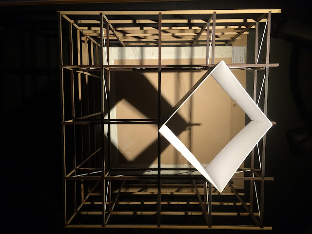
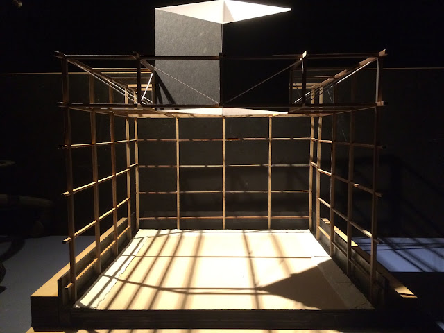
The final effect looks not bad
although not very delicacy, the whole structure is well represented....

View from the top.
3. Shelters for Roman ruins
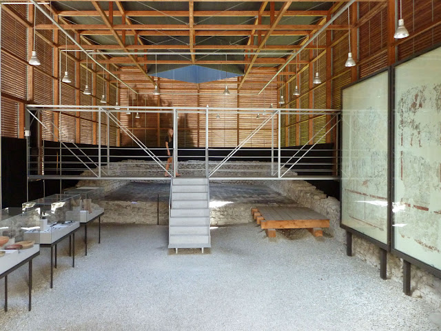
For this building I decided to make a 1:20 section model to show the structure

I calculated the size of columns and beams and drew a CAD for laser cutting.
To make sure all the members can be assembled in the right position I set notches.

Using plastic rods to represent the steel rods

The final effects
The black rod I bought was too thick, so I changed to a smaller size and with white color.
I tried to use plasticine to represent the ancient ruins, but it was damaged when I transport it home.
I used some plaster to replace it.
Final effect
Thanks a lot for all the tutors and classmates.
I learned a lot and had a lot of fun from this course.
Thank you!
Prepare Stage
The selected design element is to show how the Glue-Laminated Timber columns connect to the CLT floor plate. I decide to make a 1: 5 detail model.
I researched a lot about this building, and find the right structure system.
The construction picture
Then I make a digital model

At the very beginning, I make a digital model for the whole building and want to make a 1: 500 model because it is the tallest timber structure building in the world at the moment. And I give it up finally because in this scale I can only show the relationship between different members and how it looks like, I can't present how they connected and the why this building is so stable.
Therefore, I decided to make a 1:5 detailed model.
The metal connected part, I first tried to used metal plate to make it.

Cutting the metal plate in the right size.


Using an electric drill machine to drill hole on the metal plate and sanding it.


Then using this tool to bend the metal plate.

Using electro welding to connect metal plates together.

Finally I get a metal connection....
BUT
I give it up ..............
The connection is very complex that the upper column, lower column, and floor plate all connected to the junction, the metal connection I made can only be connected to one side and it is too small that it is very hard to represent all the details.....
So I make a digital model on rhino

And 3D print the metal part.
Sorry, I didn't take a picture...

The 3D print one can nicely show all the detail.
I can even assemble them like in real life.
By the way, I found that the CLT panel is made by multi-layer timber plates.
I use 5 layers of balsawood and use PVA to glue them together to represent this detail.
All the Parts..
2. University of Massachusetts Amherst Design building
The most interesting part of this building is the structure of its atrium
about 9m to 12 m spanning, column-free and a roof garden on top.
I decided to make a typical structure model to represent it.
The scale was a big problem, I talked a lot with my tutor.
If make a 1:10 model, it will be too big, the model will over 1 meter long.
however, if make a 1:20 model the metal members will be very small.
Finally, I decided to make a 1: 20 model.
The first step is to make a digital model in rhino


Then use the same way like the first model - 3D print all the metal connection


I don't know is this the right way to make this model. the printed components are really small.
In my digital model, all the members can be assembled.
In order to show the whole structure, I moved on in this scale.


The final effect looks not bad
although not very delicacy, the whole structure is well represented....

View from the top.
3. Shelters for Roman ruins
For this building I decided to make a 1:20 section model to show the structure

I calculated the size of columns and beams and drew a CAD for laser cutting.
To make sure all the members can be assembled in the right position I set notches.

Using plastic rods to represent the steel rods

The final effects
The black rod I bought was too thick, so I changed to a smaller size and with white color.
I tried to use plasticine to represent the ancient ruins, but it was damaged when I transport it home.
I used some plaster to replace it.
Final effect
Thanks a lot for all the tutors and classmates.
I learned a lot and had a lot of fun from this course.
Thank you!
评论
发表评论